|
|
 |
Prospective head movement correction for high resolution MRI using an in-bore optical tracking systemIntroduction The image quality in high-resolution brain scans can be compromised by head motion. Various methods have been proposed to ameliorate this problem. MRI image-based methods can only calculate corrections after acquiring an image and are therefore always lagging the motion. Navigator-based methods increase scan time and also suffer from delays between detection and correction of movement. Because of this, prospective motion correction based on external tracking systems has been proposed. Stereo optical tracking systems have been shown to give good real-time motion correction with reasonable accuracy [1]. However, there are limitations to these systems. First, these systems are placed several meters from the subject, which could make the spatial resolution low compared to a tracking system positioned closer to the (head of the) subject. This is particularly important with the high spatial resolution (~200 um) becoming available with high field MRI systems. Second, the current tracking systems need a tracking target to determine the motion parameters, such as a mouthpiece [1] or a cap [2]. This is uncomfortable for the subjects and hard to combine with close-fitting receiver arrays and/or stimuli delivery systems. We therefore designed a new motion tracking system for prospective correction of MRI.
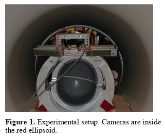
Method The optical tracking system includes two MR compatible infrared cameras (MRC Systems GmbH, Germany). The two cameras were fixed on a holder right above and in front of the head coil, Fig.1. The distance from the cameras to the object center was around 20cm. With this close view, the cameras could track features on the object directly. Also, because the spatial resolution was quite high for this setup, we could detect very small movements. Prior to using the system for motion correction a calibration is necessary to link the positions of the tracking cameras to the MRI scanner coordinate system. To do this, we designed a phantom whose inside structure consists of a grid of cubes, Fig.2. The advantage of this phantom is that it has many feature points that could be used for calibration, and the clear edges make the calibration accurate and fast. For the motion calculations a number of feature points are automatically selected on the image of one of the camera and the corresponding points are identified on the image from the other camera. After correction for the image distortion of the camera lenses, the position of these feature points can be calculated in 3D using triangulation. The changes in position of the feature points in the images are tracked over time, from which the changes in their 3D position can be extracted. Then from the collection of 3D points the translation and rotation parameters are estimated. The tracking system communicates with the MRI scanner through a TCP/IP connection. Before each excitation, the scan computer reads the current values of the continuously updated motion parameters to adjust the gradient rotation and offset phases and frequencies in the sequence to compensate for the changes in position.
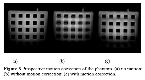
Results and Conclusions Experiments were done on a GE 7T scanner. A stability test was carried out where the system tracked a stationary object for several minutes. Motion correction results are shown in Fig.3. A multi-shot gradient echo sequence was used, with TE 4.2ms, TR 1.5s, flip angle 20. Fig.3 (a) shows the calibration phantom image with no motion. Fig 3(b-c) were acquired with motion during the scan, where (b) is uncorrected and in (c) motion is corrected. The motion was about a 7 mm step in the vertical direction in the image, approximately performed at the moment the center of k-space was acquired. The results suggest that the new system has sufficient precision to be used in high resolution MRI, where head motion is one of the main resolution limiting factors. We developed an optical motion correction system to improve image quality for MRI. Experiments were done on a phantom to test feasibility. The system is stable and able to accurately correct relatively large motions during the scan.
References [1] Zaitsev, M., Dold, C., Hennig, J., Speck, O., NeuroImage., 31 (3), 1038-50, 2006. [2] Tremblay, M., Tam, F., Graham, S.J., Magn. Reson. Med. 53 (1), 141-9, 2005.
|
| [Home] [Biography] [Research] [Teaching] [Industry Exp.] [Lab. Personnel] [Collaborators] [Publications] [Links] |

